5. Rebuilding the coil-pack
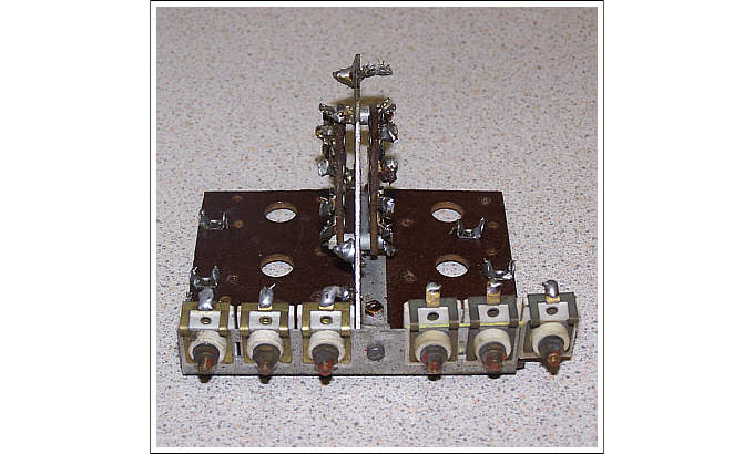
Next came the task of stripping the existing A22 coil-pack.
After careful removal of all the components I added an extra trimmer capacitor to the stripped board. This was necessary due to all three coils in the aerial section requiring a tracking trimmer.
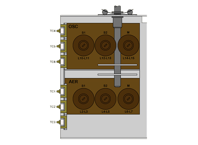
As the coil-pack in an original A22T also has this sixth trimmer, I adopted the same layout.
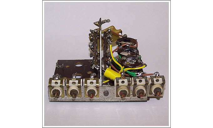
I modified the mounting arrangement used by the group of two existing trimmers to securely hold it in place. This leaves the trimmer standing a few millimetres higher than the others and off of the end of the board, but since its fixing was mechanically sound I considered it acceptable.
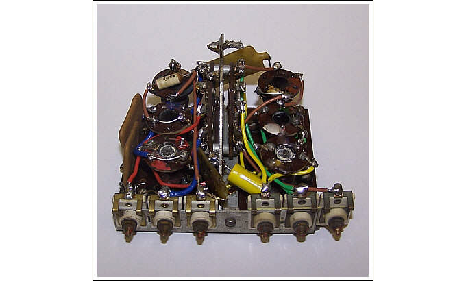
I began the rebuild with the slightly less complicated "Aerial" side of the board, adding the three coils one at a time and soldering the required connections between the bank of trimmers running down the side and the band-switching wafer mounted in the middle.
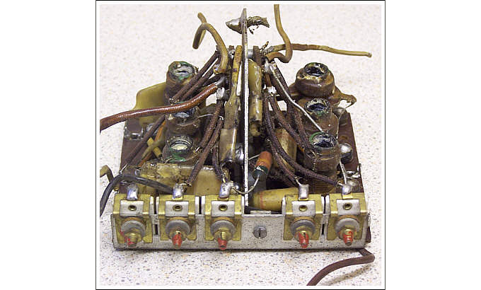
Continuing in similar fashion, I rebuilt the "Oscillator" side of the coil-pack. This section was more difficult due to having to accommodate the large padder capacitors in the limited space available.
Note: the two large 6800 pF 1% mica capacitors on the left hand edge. These are connected in series to make-up the calculated 3400 pF padder value required for the S2 oscillator range.
I should add that none of the original coils and padder capacitors were used in the rebuild and have been carefully saved, even the medium wave coils used were reclaimed components. Therefore, these coil-pack modifications are completely reversible should it be so desired.